Mechanical design basis
The output energy is proportional to the stress caused by a piezoelectric film. The thickness of the film can also be determined from the mechanical strength in order to obtain the optimal signal to select the proper film thickness. Thicker film has higher voltage but less capacitance. Therefore, thinner film and flexible inert material (e.g. polyester, see LDT1~028K) may be better than single thick film. Any membrane area without stress is a capacitive load on the effective working area, and the smaller the better it is if needed.
Most of the metal layers are easy to rust, especially when transportation, thin coating or laminating is used to maintain the surface quality. In laminating and assembly, acrylic gum is often used to synthesize rubber resin, epoxy resin and cyanoacrylate. In some designs, the outer metal layer or the conductive substrate is used as the electrode, and the unmetallized piezoelectric film is used to its own advantages. The outer metal layer can directly contact the unmetallized film to collect the charge, or, in AC signal application, the capacitive coupling can be achieved through thin tape or epoxy resin layer. The shape of the electrode is particularly useful for determining the specific effective working area on the whole continuous membrane material, and also for leaving the blank blank space in the cutting part when cutting the components. The design of the upper and lower electrode leads can prevent the unexpected problems of the piezoelectric film caused by the influence of the lead contact. It is also easy to take the low cost and penetrating lead method (the pressing terminal or the hollow rivet).
Mechanical and electrical comprehensive design basis
The capacitive nature of piezoelectric film determines its vulnerability to electromagnetic interference. As the output signal level decreases, this becomes more important. But when the output signal is very high or the piezoelectric film is driven under unimportant conditions, the electromagnetic interference can not be considered. The interference of AC power supply may be a problem for unshielded devices. Another potential problem is that when an electrode is being driven and the other is receiving a vibration signal, it is necessary to avoid "crosstalk".
In the case of the use of a shielding device with a coaxial cable produced by the MSI company, all of the above problems will be solved. However, any device can avoid interference as long as it takes simple measures.
The frequency that is not needed can be filtered. If the sensor is mounted on the conductive substrate, it will form a half grounding envelope, while the outer electrode will form the other half envelope. The small shielded cable has been commercially available, and it can be used to replace twisted pair wire. The connection point itself should also be paid attention, as that area is also easily disturbed by EMI.
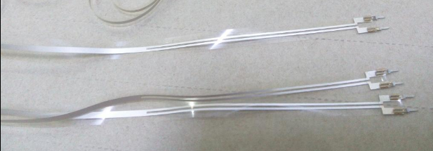
MSI has developed a durable wire connection technology, most of which have a pre - connected lead. As mentioned earlier, coaxial cable can usually be used, but it must be interfaced with very thin flexible materials. If the connection point has vibration, it will import certain sound effect to the sensor, so it is necessary to reinforce the connection point of the lead.
The thin copper foil with conductive adhesive can be non permanent connection made great. The contact resistance of the 1cm2 area is about a few millieu (M omega). Like flexible circuits, crimping terminals are often used in stagger electrodes, but thin films need structural reinforcement to achieve good results. Polyester reinforcement is a commonly used reinforcement connection method at lead connections. The contact resistance is slightly reduced by the stiffened plates between the terminals and the electrodes. It is generally 150~500 millieu. Micro rivets, hollow rivets even nuts, bolts and gaskets are connected with high strength and good contact resistance, generally less than 100 millieuropean. These techniques can be used to connect the cable with the welded sheet and can be used directly on the printed circuit board.
Methods using the wire clamp, can be directly clamped in the conductive pattern of the printed circuit board or with a conductive adhesive, ZEBRA joints, welding sheet and gasket were successfully applied. The direct connection with the silver (conductive) epoxy resin is also good, but the curing time is required. In order to get the best effect, the curing temperature is usually improved.
As mentioned earlier, other materials can also be made as electrodes, such as conductive adhesives or foamed materials. In some cases, it is feasible to adopt a capacitive coupling through the rubber layer, allowing some special sensors to be designed without any lead connection.